Working principle of servo motor and servo drive debugging method
First, the overview of servo motor
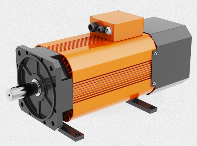
Servo motor refers to the engine that controls the operation of mechanical elements in the servo system, and is an indirect speed change device that supplements the motor.
Working principle of servo motor and servo drive debugging method – Hirden servo 80 flange 750wservo motor
The servo motor can control the speed, the position accuracy is very accurate, and the voltage signal can be converted into torque and speed to drive the control object.
The rotor speed of the servo motor is controlled by the input signal, and can respond quickly, in the automatic control system, used as an executive element, and has the characteristics of small electromechanical time constant, high linearity, starting voltage, etc., which can convert the received electrical signal into angular displacement or angular velocity output on the motor shaft.
Divided into two categories: DC and AC servo motors, its main feature is that when the signal voltage is zero, there is no rotation phenomenon, and the speed decreases uniformly with the increase of torque.
brushless coreless motor – 16mm coreless servo motor High precision encoder 1636 coreless brushless planetary geared motor video
Second, the working principle of the servo motor
1. The servo system is an automatic control system that enables the position, orientation, state and other output controlled quantities of the object to follow any change of the input target.
Servo mainly relies on pulses to position, basically it can be understood that the servo motor receives 1 pulse, will rotate the angle corresponding to 1 pulse, so as to achieve displacement, because, the servo motor itself has the function of sending pulses, so the servo motor rotates at an angle, will send out the corresponding number of pulses, in this way, and the servo motor receives the pulse to form an echo, or called closed loop, so that the system will know how many pulses sent to the servo motor, and at the same time how many pulses are received back, so, It can accurately control the rotation of the motor, so as to achieve accurate positioning, which can reach 0.001mm.
DC servo motors are divided into brushed and brushless motors. The brushed motor has low cost, simple structure, large starting torque, wide speed regulation range, easy control, and requires maintenance, but it is inconvenient to maintain, produces electromagnetic interference, and has requirements for the environment. Therefore, it can be used in general industrial and civil applications that are sensitive to costs.
The brushless motor has small size, light weight, large output, fast response, high speed, small inertia, smooth rotation and stable torque.
The control is complex, easy to realize intelligence, and its electronic commutation mode is flexible, which can be square wave commutation or sine wave commutation.
The motor is maintenance-free, has high efficiency, low operating temperature, little electromagnetic radiation, long life, and can be used in various environments.
2, AC servo motor is also brushless motor, divided into synchronous and asynchronous motor, the current motion control generally uses synchronous motor, its power range is large, can do a lot of power. Large inertia, low maximum rotational speed, and rapid decrease as power increases. Therefore, it is suitable for low-speed and smooth operation applications.
3. The rotor inside the servo motor is a permanent magnet, the drive controls the U/V/W three-phase electricity to form an electromagnetic field, the rotor rotates under the action of this magnetic field, and the encoder feedback signal of the motor comes with the driver, and the drive compares with the target value according to the feedback value and adjusts the angle of rotor rotation.
The accuracy of the servo motor depends on the accuracy of the encoder. The difference between AC servo motor and brushless DC servo motor in function: AC servo is better, because it is sine wave control, and the torque ripple is small. DC servos are trapezoidal waves. But DC servos are simpler and cheaper.
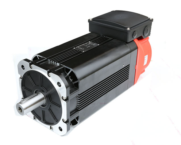
Working principle of servo motor
Third, the debugging method of servo motor
1. Servo motor initialization parameters
Before wiring, initialize the parameters.
On the control card: select the control method; Clear the PID parameter to zero; Make the enabling signal turn off by default when the control card is powered on; Save this state to ensure that it is the status when the controller is powered up again.
On the servo motor: set the control mode; Setting enablement is externally controlled; The gear ratio of the encoder signal output; Set the proportional relationship between the control signal and the motor speed. In general, it is recommended that the maximum design speed in servo operation correspond to a control voltage of 9V.
For example, UIMOTION is to set the speed corresponding to 1V voltage, the factory value is 500, if you are only going to make the motor work below 1000 rpm, then, set this parameter to 111.
2. Servo motor wiring
Power off the control card and connect the signal line between the control card and the servo. The following lines must be connected: the analog output line of the control card, the enable signal line, and the encoder signal line of the servo output.
After reviewing the wiring for errors, the motor and control card are powered on. At this time, the motor should not move, and can easily rotate with external force, if this is not the case, check the setting and wiring of the enabling signal.
Turn the motor with an external force to check whether the control card can correctly detect the change in the position of the motor, otherwise check the wiring and setting of the encoder signal.
3. Test the direction
For a closed-loop control system, if the feedback signal is not directed correctly, the consequences are sure to be catastrophic. Turn on the enable signal of the servo through the control card. This is where the servo should turn at a lower speed, which is the legendary “zero drift”.
Generally, there will be instructions or parameters on the control card to suppress zero drift. Use this command or parameter to see if the speed and direction of the motor can be controlled by this command. If it cannot be controlled, check the parameter settings of analog wiring and control mode.
Confirm that positive numbers are given, the motor is forward rotating, and the encoder count is increased; Negative numbers are given, the motor reverses, and the encoder count decreases. If the motor is loaded and the stroke is limited, do not use this method.
The test should not give too large voltage, it is recommended to be below 1V. If the orientation is inconsistent, the parameters on the control card or motor can be modified to make them consistent.
CAN communication 28 stepper servo integrated machine
4. Inhibit zero drift
In the closed-loop control process, the existence of zero drift will have a certain impact on the control effect, and it is best to suppress it.
Use the parameters on the control card or servo to suppress zero floating, and carefully adjust the speed of the motor to close to zero. Since the zero drift itself also has a certain randomness, it is not necessary to require the motor speed to be absolutely zero.
5. Establish closed-loop control
Again through the control card to release the servo enable signal, input a small proportional gain on the control card, as for how much is small, this can only be based on feeling, if you are really not assured, enter the minimum value that the control card can allow.
working principle of servo drive
Turn on the enable signals for the control card and servo. At this time, the motor should already be able to roughly act according to the motion instructions.
6. Adjust closed-loop parameters
Fine-tuning the control parameters to ensure that the motor moves in accordance with the instructions of the control card is a necessary work, and this part of the work is more experience, which can only be omitted here.