Low Voltage Stepper Driver DM545A Manual – 2-Phase Driver Datasheet.
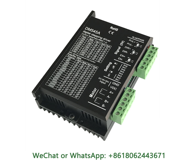
DM545A stepper driver with lower motor heating, running noise and higher smoothness at low cost.
The low-voltage stepper motor driver design adopts high-speed motion control CPU to realize fast adaptive control algorithm and high-frequency carrier bipolar constant current chopping sine wave subdivision drive control, and the driver has control characteristics such as high precision, strong torque, low noise, and wide speed regulation.
Low Voltage Stepper Driver DM545A Manual – 2-Phase Driver Datasheet
motorforum.rfidepc.com is a manufacturer of stepper motors, servo motors, stepper drives and servo drives, providing servo and stepper motion control products for users around the world.
Low Voltage 2-Phase Stepper Driver DM545A Manual – DM545A Driver Datasheet Specifications
2-phase stepper driver function description:
| Low voltage 2-phase stepper drive function | Operating instructions |
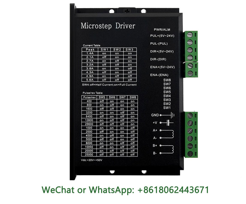
| Microstep subdivision settings | The SW5-SW8 four DIP switches set the number of driver microstep subdivisions, which has a total of 15 microstep subdivisions. When the user sets up a microstep subdivision, the drive should be stopped first. For the specific number of microstep subdivisions, please refer to the driver layout. |
| Output subdivision settings | The driver output current is set by SW1-SW3 three DIP switches, and its output current has a total of 8 levels. For specific output current settings, please refer to the driver layout. |
| Automatic half-flow function | The SW4 allows the user to set the automatic half-flow function of the drive. OFF means that the quiescent current is set to half of the dynamic current, and on means that the quiescent current is the same as the dynamic current. In general use, SW4 should be set to off, so that the heat generated by the motor and drive is reduced and the reliability is improved. After the pulse train stops, the current is automatically reduced to about half (60% of the actual value) in about 0.4 seconds, and the heat generation is theoretically reduced to 36%. |
| Signal interface | PUL+ and PUL- are the positive and negative terminals of the control pulse signal; DIR+ and DIR- are the positive and negative terminals of the directional signal; ENA+ and ENA- are the positive and negative terminals of the enable signal. |
| Motor interface | A+ and A- connected stepper motor A-phase windings positive and negative terminals; B+ and B- connect the positive and negative ends of the B-phase windings of the stepper motor. When the A and B two-phase windings are exchanged, the motor direction can be reversed. |
| Power connector | It adopts DC power supply, the working voltage range is recommended to be 20-40VDC, and the power supply power is greater than 100W. |
| indicator | The drive has two LEDs, red and green. Among them, the green light is the power indicator, and the green light is always on when the drive is powered on; The red light is a fault indicator, and when there is an overvoltage and overcurrent fault, the fault light is always on. After the fault clears, the red light goes off. When a drive fails, only power-on and re-enable clears the fault. |
| Installation instructions | The external dimensions of the driver are: 118mm, 75.5mm, 34mm, and the mounting hole distance is 112mm. Both horizontal and vertical installation is possible, vertical installation is recommended. When installing, it should be placed snugly against the metal cabinet to facilitate heat dissipation. |
Low Voltage Stepper Driver DM545A Manual – 2-Phase Driver Datasheet
2-phase stepper driver current setting:
| Output current | Reference current | SW1 | SW2 | SW3 |
| 1.00A | 0.71A | on | on | on |
| 1.46A | 1.04A | off | on | on |
| 1.91A | 1.36A | on | off | on |
| 2.37A | 1.69A | off | off | on |
| 2.84A | 2.03A | on | on | off |
| 3.31A | 2.36A | off | on | off |
| 3.76A | 2.69A | on | off | off |
| 4.20A | 3.00A | off | off | off |
Microstep subdivision settings:
| Steps/turn | SW5 | SW6 | SW7 | SW8 |
| 400 | off | on | on | on |
| 800 | on | off | on | on |
| 1600 | off | off | on | on |
| 3200 | on | on | off | on |
| 6400 | off | on | off | on |
| 12800 | on | off | off | on |
| 25600 | off | off | off | on |
| 1000 | on | on | on | off |
| 2000 | off | on | on | off |
| 4000 | on | off | on | off |
| 5000 | off | off | on | off |
| 8000 | on | on | off | off |
| 10000 | off | on | off | off |
| 20000 | on | off | off | off |
| 25000 | off | off | off | off |
Different effects:
1. Stepper motor controller is an electronic product that can send out an average pulse signal, and the signal it sends out enters the stepper motor driver, which will be converted into the strong current signal required by the stepper motor by the driver and drive the stepper motor to run.
2. Stepper motors have a wide range of applications in control systems. It can convert the pulse signal into angular displacement, and can be used as an electromagnetic brake wheel, electromagnetic differential, or angular displacement generator. The driver said that it received a pulse signal, and each time a pulse was received, the stepper motor controller would drive the motor to turn a fixed angle, which because of this feature, the stepper motor will be widely used in various industries now.
stepper motor driver manufacturer
3. Stepper motor driver is an actuator that converts electrical impulses into angular displacement. When the stepper driver receives a pulse signal, it drives the stepper motor to rotate a fixed angle (called “step angle”) in the set direction, and its rotation is run step by step at a fixed angle. The amount of angular displacement can be controlled by controlling the number of pulses, so as to achieve the purpose of accurate positioning; At the same time, the speed and acceleration of motor rotation can be controlled by controlling the pulse frequency, so as to achieve the purpose of speed regulation and positioning. The principle of stepper motor driver is powered by unipolar DC power supply. As long as the windings of each phase of the stepper motor are energized in the appropriate timing, the stepper motor can be turned on step by step.


Joseph –
DM545A drive is of good quality, thanks to the seller