1. Start preparation: press the button SB2, the contactor KM coil is energized, the KM main contact and two normally open auxiliary contacts are closed, the KM main contact is closed for the inverter to turn on the main power supply, one KM normally open normally open auxiliary contact is closed, the locked KM coil is energized, and the other KM normally open auxiliary contact is closed, which prepares for the relay K intermediate A coil to be energized.
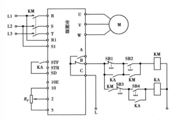
2. Forward control: press the button SB4, the relay KA coil is energized, 3 KA normally open contacts are closed, 1 normally open contact is closed to lock the KA coil to get electricity, 1 normally open contact is closed short button SB1, there is a normally open contact closed connection STF, SD terminal, equivalent to STF terminal input forward control signal, inverter U, V, W terminal output forward power supply voltage, drive motor running in the forward direction. By adjusting the potentiometer R connected to this terminal, the output power frequency of the frequency converter changes, and the speed of the servo motor also changes.
3. Inverter abnormal protection: If the inverter fails during the abnormal period, the internal equivalent normally closed switch between the B and C ends of the inverter is disconnected, the contactor KM coil is de-energized, the KM main contact is disconnected, the inverter input power is cut off, the inverter is protected, and the relay KA coil is also powered off, and the 3 KA normally open contacts are disconnected.
4. Shutdown control: when the inverter is working normally, press the button SB3, the KA coil loses power, the KA 3 normally open contacts are disconnected, one of the KA normally open contacts is disconnected and cut off STF, SI) terminals are turned on, the inverter stops the output power supply, and the servo motor stops.